Stringer - Adding breaklines and polylines to the Surface ModelGoals:Understand how Stringer works to add breaklines to a model Learn how to use the Profile Editor to control how the software will add 2D and 3D polylines for display and modelling purposes Learn how to add breaklines to the model using Stringer Introduction - StringerStringer works by connecting up points that have a common point code and string number with 2D and/or 3D polylines and adding the 3D polylines to a surface model, working from lowest point number to highest point number. Surveyors can automatically control the 'breaking' of strings by assigning different string numbers at the end of the point code description. In order for Stringer to perform to its optimum, users will generally need to do the following: Create and use a drawing template (.dwt) file that includes all the layers you want to use to distinguish different features (eg: edge of pavement, top of bank, etc). In Civil 3D this will also include point styles (which control how point objects will display), point label styles (which control how the labelling for points is displayed) and a description key set file (which associates point codes to point styles and point label styles). Use the Profile Editor to set the point codes for which Stringer will create 2D polylines (for display on screen) and/or 3D polylines (for adding breaklines to a surface model). This includes setting what layers each of the features will come in on. If this profile isn’t correctly set then when the Join all codes function is used you won’t get any crossing breaklines because there won’t be any polylines added to the surface.
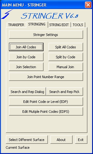
Setting up Stringer - the Profile EditorIn order to control which point codes are stringable in both 2D and/or 3D users need to use the Profile Editor. The Profile Editor is used to tell the software which point codes should be used for creating 2D and/or 3D polylines. Step 1: To understand how the Profile Editor works, start the command STR
or select the programme Icon
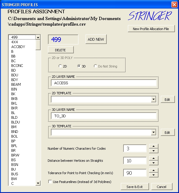
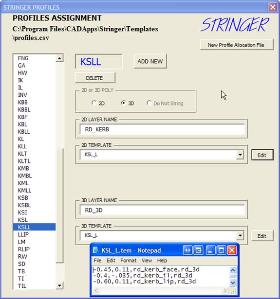
This form is used to tell Stringer which point codes to connect up with 2D and/or 3D polylines and also to include Templates (offset polylines). The full list of point codes used are shown on the left. This file is an Excel spreadsheet saved with .CSV extension (comma delimited). Click on EB (Edge of Bitumen Code) to see how Stringer will join up this point code. Under the heading '2D or 3D POLY' the 3D button is ticked on - in this instance a 2D polyline and 3D polyline is to be created connecting the points with code EB*. Under the title '2D Layer Name' you would normally type in the name of the layer you want the 2D polyline to go on - it is usual to reference to a layer that exists in the drawing. Under the title '3D Layer Name' type in the name of the layer you want the 3D polyline to go on (e.g. TO_3D) - it is usual to reference to a layer that exists in the drawing for ease of turning off that layer and just leaving the 2D linework there for your final plan. The 3D polylines are only used to add breaklines to the surface model and the layer they go on isn’t important. Click on Add New to create extra point codes for Stringer. You can also assign 'templates' to your point codes, which work as offset polylines to the polyline connecting the points as shown below:
Step 4: Click on the point code KSLL to view it. Note that
for the 2D and 3D polylines created that Stringer will also create an offset
polyline as per the 'Template' named KSL_L. You can create as many templates as you require. To select a
template use the drop down lists. You
can edit a template by clicking on the Edit
button next to the name of the template. Click on
edit to view the KSL_L
template. This opens up a file in
notepad. The template is described
in a comma delimited text file as follows: Offset from polyline (negative to the left), change in elevation, 2D layer to use, 3D layer to use. Each line in the template represents a new polyline that will be created by the software. The KSL_L
template here describes a barrier kerb and channel comprising of an invert, top
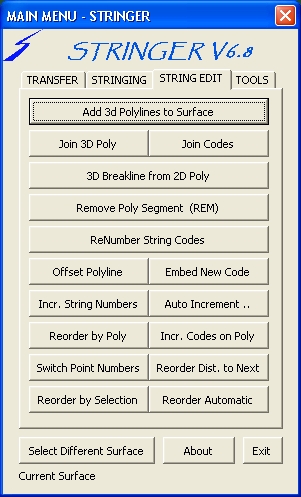
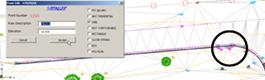
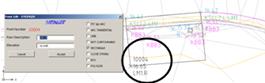
of kerb and back of kerb being represented by three offset polylines. Templates must be saved with extension *.TEM. Templates are used to create parallel polylines to the surveyed line, whether as 2D drafting or as 3D terrain modelling breaklines. The template files must have the file extension TEM and be placed in the Stringer Working Folder\Templates folder. Step 5: The point code settings have already been customised for this dataset. Simply click on the cross at the top right of the form to return to Civil 3D. Running StringerAt this stage no breaklines have been added to the surface model Having confirmed the settings for Stringer, the next step is to run Stringer for join up all the points and automatically add breaklines to the model. Start the command STR
Note: The Civil 3D Surface that breaklines will be added to by Stringer
is shown at the bottom of the form. If
more than one Civil 3D Surface exists, use the command button Select
Different Surface to set which surface to add breaklines to, if
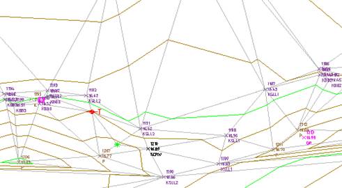
required. To add breaklines to your surface model, click on the Join All Codes Button The software will add breaklines to the model and will update the surface upon addition of each breakline. At the end of the process you should have a completed a Surface model including polylines for each survey feature line, on layers specified in the Profile Editor form. Make sure profile Editor form has been set to the correct profile before hitting the Join All Codes otherwise crossing breaklines won’t show up in the Panorama window Once you have used Stringer to create breaklines and/or to edit surface breaklines, it is strongly recommended that the surface is manually rebuilt. To do this right click on the surface name in the Toolspace (Prospector tab) and select Rebuild. Join All CodesBefore Join All Codes
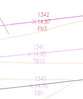
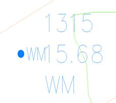
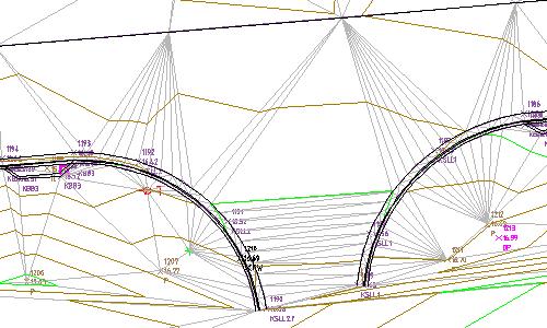
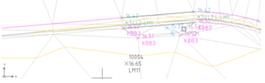
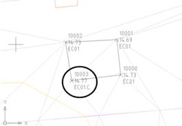
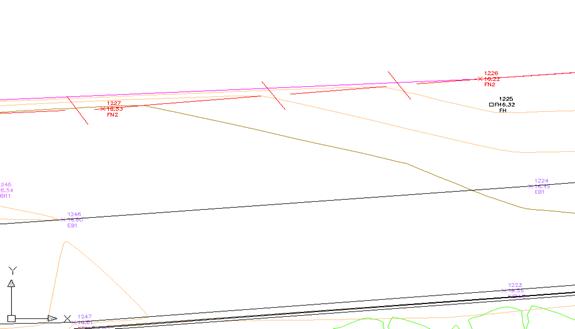
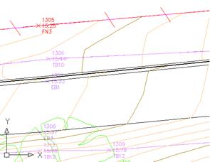
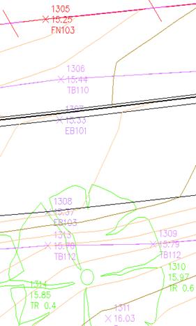
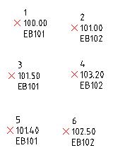
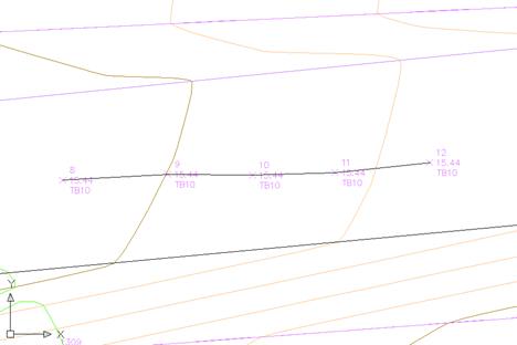
There are no breaklines working on the surface and the software is using its own algorithm to create the surface triangulation based on the proximity of points to each other, regardless of point codes. The point code KSL is supposed to be used as a breakline in the surface model and has included a (Template) offset polylines to describe the kerb and channel. Both the contours (brown and green) and the triangulation (light grey) are displayed for the surface. The triangulation to the SCRW (black colored point) on the screen - this is crossing the kerb line. After Join All Codes
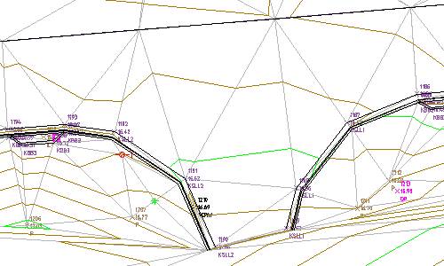
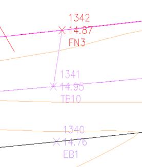
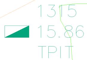
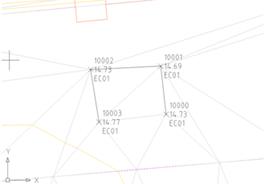
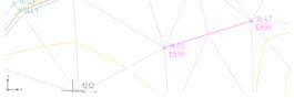
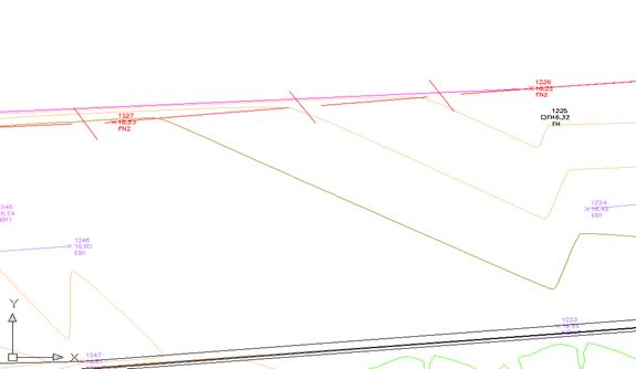
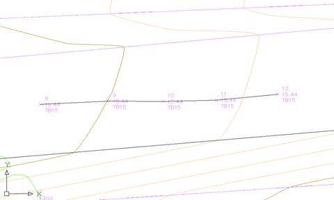
Breaklines have been added to the model and the surface has automatically updated to reflect the changes. The triangulation now runs along the kerb line to respect this breakline and that breaklines have been included to model the kerb and channel The kerb returns are currently represented by chords instead of arcs. It is preferable to create the kerb return using arcs instead of straight segments. This can be addressed by editing some of the point codes and adding in Stringer feature coding - this can be done in the field by adding a . separator at the end of the point code and a letter or by editing the points in Civil 3D. Join By Code
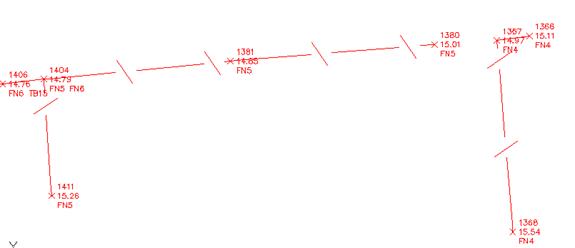
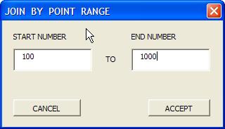
This function will join the code from picking just one of the points on the screen that has the same code and will use string number to join that code together. Same Code Same String Number e.g. FN5 with FN5 Manual JoinThis function will allow you to select any 2 points in the drawing and join
them together, adding a 2d polyline and 3d manual breaklines to the surface. The first
point you select will be the layer the polylines will go onto. Under
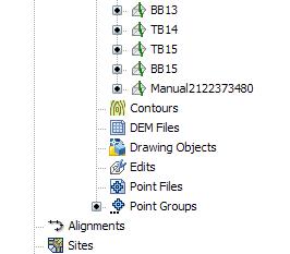
Surfaces in the Prospector Tab expand out the breaklines cross and you will see
a manual breakline added
Before
Manual Join
After Manual Join What
gets added to the breaklines in the Surface
Join
|
|
|
|
Additional Stringer feature codes are normally assigned to the point codes as they are taken out in the field, however you can always adjust the point codes to re-create breaklines (and adjust the surface model) and polylines as desired.
Step
7:
To edit a point, start the Stringer Main Menu, change to the Stringing
tab and click on the command button Edit
Point Code or Level. If you like
to use the keyboard then type EDP
in the commandline as a keyboard short cut.
Step
8:
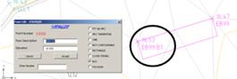
Select a point on screen to edit. For
the purpose of this tutorial select the point number 1190 (south-west corner of
the intersection edge of bitumen - coded KSLL).
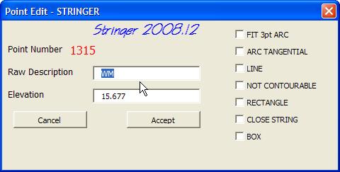
This will open the Points Editing form:
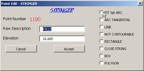
You may re-enter the point code altogether, or you may select one of the Parameters, which are added with a . separator. Parameters are normally entered in the field, but we all need to edit sometimes. The editing of the points is dynamic: once the code is changed, the strings and breaklines are updated.
Step
9:
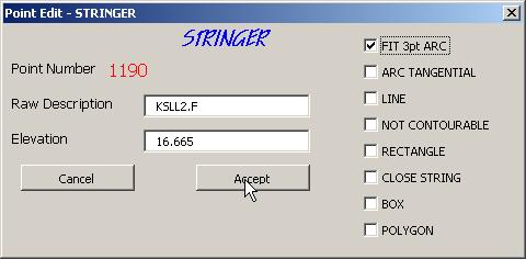
Click on the button to FIT
3pt ARC.
This will adjust the point code to add a .f - Stringer will change the
breaklines to make 3 point arcs for the next points. The arc will continue until
you add a .L to the last point on the arc and then the arc will return to a
straight line.
To
make the edit and adjust the breakline and surface model, click on the button Accept.
Note:
After Stringer adjusts the breaklines for the surface it is strongly
recommended that you Rebuild the
surface to update it
Step
10:
Make the following changes to points (editing the Raw Description):
|
Point
No. |
Raw
Description |
|
1186 |
KSLL1.F |
|
1190 |
KSLL.F |
|
1193 |
KSLL.L |
Note:
Stringer will delete the breaklines from the selected surface and
re-create them using the changed point codes.
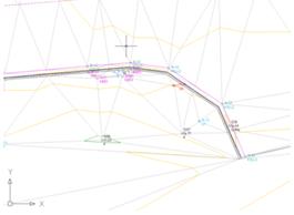
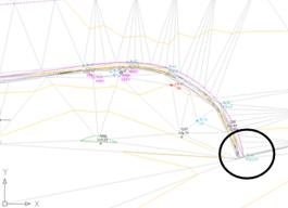
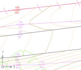
The resultant surface model is as follows (part shown only):
Note how the kerb and channel now follows an arc, and 3D breaklines have been automatically added with a series of short chords to accurately model the curvature of the kerb returns.
Stringer
Code Suffix
.f
- Fit 3pt ARC
.a
- Arc Tangential
.l
- line between points
.r
- rectangle
.c
- close string to first point
.b#
- box (specify number of sides - between two points)
.n
- rotate a point symbol to align to the next point taken (no tick box option)
.p
- rotate a point symbol to align to the previous point taken (no tick box
option)
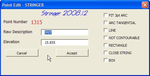
The Description Key Set has to be set to rotate on points (TPIT) that may be rotated to say a footpath so that when .n & .p are used in the field civil3d will be able to apply the rotation on those points to either the next or previous point taken.
Multiple coding is acceptable in Stringer - to do multiple coding separate the code/string number by a space. Eg: EB01 KSLL01 will dual code the point with two descriptions.
Note:
When using multiple string coding, every unique string code must exist in
the drawing/project as the first of multiple string codes at least once.
Stringer Point Codes Examples (Partial List - the really good ones)
|
Stringer Code |
Before Adding Stringer Code |
After Adding Stringer Code |
|
.f |
|
|
|
.l |
|
|
|
.r |
|
|
|
.c |
|
|
|
.b# |
|
|
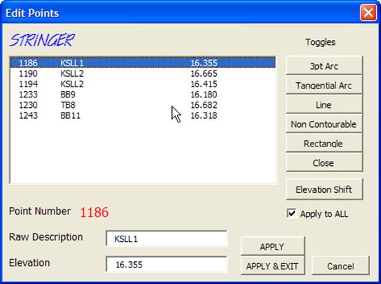
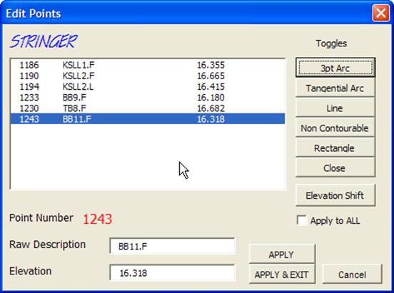
Edit Multiple Point Codes (EDPS)
Allows
the user to edit the Raw Description of Multiple Points, adding or removing the
String Parameters.
To
add or remove a String Parameter, simply check or uncheck the box for the
appropriate parameter. For example, clicking on the 3pt Arc button will
cause the .F parameter to toggle on or off. If the Apply to All is on, then the
selected parameter is applied to all of the selected points. If it is not
ticked, then only the currently highlighted point is affected.
You
can manually alter the codes in the Text Edit box as well. Elevations and Point
Numbers can not be altered.
Altering
the parameters will cause the program to search for effected polylines, erasing
the old polylines and reprocessing the code effected. This is referred to
as Interactive Editing.
You
must click on the Apply button for the edits to take effect. Pressing Exit does
not automatically apply the changes.
Elevation
Shift
Pressing
the Elevation Shift button reveals the Elevation Shift entry box. Enter the
amount that you wish to alter the current elevations by. Again, the changes are
not applied to the drawing until you press Apply, although the elevations in the
display will reflect the change. Press the escape key to cancel the elevation
shift entry.
This
routine can be accessed from the keyboard by typing EDPS
|
|
|
|
|
|
Add 3D Polylines to the Surface
Allows
the user to select 3D polylines to be added to the current surface as breaklines
Join 3D Poly
Allows the user to join two selected lines/polylines to make one 3D polyline.
If the two objects don't join at the ends this command will create the necessary link segment.
3D Poly from 2D Poly
Allows the user to create a 3D polyline from a 2D Polyline passing through points on the surface. The created 3D polyline will be created on a layer with the same name as the 2D polyline with the suffix _3D. For example if the 2D polyline was on a layer RD_EB then the 3D polyline will be created on RD_EB_3D
Remove Poly Segment
Select a 3D polyline segment and the segment is erased leaving the remaining components of the polyline in the drawing. If the polyline was not closed then two new polylines will be created
Offset Polyline
Allows the user to select an existing polyline and then select a template to be drawn on that polyline. If a 3D polyline is selected then the software will offset with 3D polylines and add them to the surface. If a 2D polyline is selected then the software will offset 2D polylines only. If no template is selected (selecting Cancel at the template selection dialog box) then the user can specify the offset required. When a 3D polyline is selected, the user will be prompted for a horizontal and vertical offset.
|
|
|
Polyline Offset Before |
Polyline Offset After |
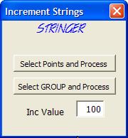
Incr. String Numbers
This
command found on the String Edit Tab is primarily used for multiple day jobs
where starting at 1 for a string number on each of the different days doesn’t
make you have to remember the string number from the previous day. You can add a
Number onto the all string Numbers to make individual days have a unique string
number e.g. 40301–403101
Select
this command and the following will display as shown below
|
|
|
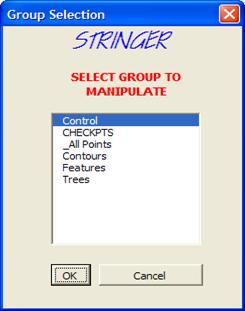
There
are 2 ways to Increment Points, either by Point Selection or by Point Group. By
Point Group you get to choose which point groups will be incremented but
majority of time it will be All_Points so it corresponds with the individuals
days work, the other is to select individual point to increment as required.
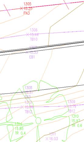
Once you have incremented your strings it will look like below
|
|
|
|
Increment
Before
|
Increment
After |
Embed New Code
Used for when a new string code needs to be inserted into an existing string
code, such as replacing a section of kerbing with a crossover. The programme
will add the new code to the selected points (automatically finding a unique
string number for the code). It will then find a new unique string number for
the continuing string.
|
|
|
|
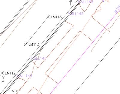
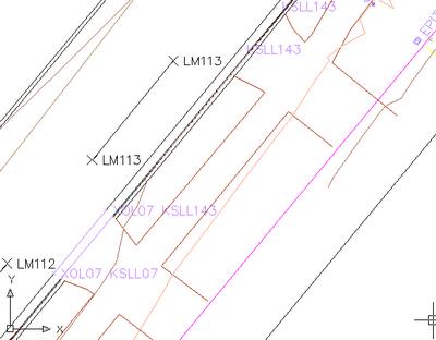
Here we have embedded XOL (Cross over Left) into the string KSLL143. Notice that the second (and subsequent) points have had the code KSLL143 changed to KSLL07, which was the next unique string number for code KSLL.
Auto Increment
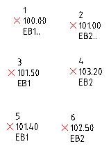
This command allows the user to automatically increment string numbers for points of common string codes in point number order. Using EB1.. again in the above example would result in Stringer creating a new, unique, string number that would be applied to all subsequent points with code EB1
Increment Codes on Poly
Allows you to select a polyline which has Civil3d points at each vertex with the intention of changing the raw description of each of those points based on the new description you enter. This is especially useful for jobs that have been manually strung and you would like the points to reflect the string codes
Before
After
Re-Order Distance to Next
Reorders the points with the same code based on the shortest distance to the next point. After selecting the first point (which also sets the code to scan for unless you select a second point which nominates the code to scan for: this is for when the first point has multiple codes) the programme automatically reorders the point numbers based on the next nearest point
Re-order
By Poly
Re-order Point Numbers based on the polyline passing through the civil3d points in the drawing
Switch
Point Numbers
Simply allows the user to select 2 points and switch the point numbers between those 2 points. Intended for when a couple of points are surveyed out of sequence.
Allows the user to select a range of points in the order that they would like the point numbers to increase. It uses the point numbers of the points selected and simply reorders them so that they increase in the same order as the order they were selected in. Intended for when a series of points on a string line have been surveyed out of sequence.
Re-order Automatic
Reorder Points either by angle or linear distance. Angle option orders in an Anti Clockwise direction based on a start point, centre point, and code. After selecting the point which is the start point for the ordering, you select the centre point about which the ordering is to be calculated. The simplest case for this is a roundabout where the point numbers are not in the correct order. This routine will renumber the points so the string line is correct. If you do not select a centre point then linear sorting by distance is used whereby points are reordered in ascending distance from the start point.
Surface - Adding a Boundary
The final part of the process is normally to add a boundary around the surface to limit the extents of triangulation. To add a boundary first draw a closed 2D polyline that crosses the triangles to be removed from the surface model. Right click on the word boundary in the Toolspace under the Surface name and select Add from the shortcut list. Fill in the following form:
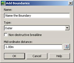
Select the closed 2D polyline on screen to trim up the outer boundary of the model.
There are 2 methods when using boundaries and they are:
'Non-destructive breakline' - brings the triangulation up to the edge of the polyline
Destructive Breakline – Trims all the triangles that touch the outer boundary polyline and leaves an offset from that boundary line. Therefore the full triangle that was touching the outer boundary line will be removed leaving an irregular boundary.
Once you have the where you want it, you can actually Extract Objects from a
Surface (whatever contour styles are shown) and extract a 2d line Border from
that surface boundary specified. Delete the previous polyline boundary and add a
new boundary from the newly extracted border. Now you have an exact boundary
that you require.
Point Group Editing
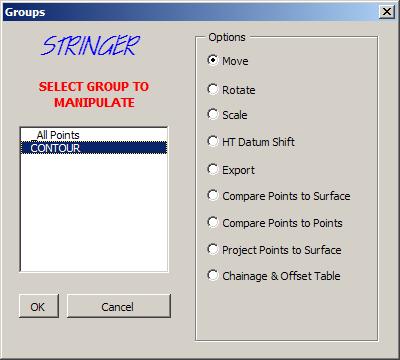
Bulk edits to points can be undertaken by using the Point Group Editing tools.
The Export option enables the user to create a points file from the selected points - a number of file formats can be generated for direct upload into survey data equipment.