Stringer - Behind the Scenes
Procedure - Stringer Program in Civil 3DStringer is the main program in this suite of programs. Its interface allows a number of related functions to be carried out. Brief DescriptionThe Stringer program is designed to make stringing of survey data easy in the AutoDesk Civil 3D environment. The program uses the raw point codes in the drawing for creating polylines, amending symbol alignments, and creating offsets (both 2D and 3D). The points can be selected manually, as a point range, or all points. You may also nominate multiple string codes to a single point, such as when an edge of bitumen joins to a concrete path. The codes are interrogated and those with numeric suffixes are regarded as stringable. With this system points can be strung even if not provided for in the settings file, Profiles.csv. This file allocates the layers to be used for the strings. Parameters associated with the points and strings can be used to enhance the polylines drawn by the program. Process
|
![]()
String Parameters
.A Arc. An arc tangential to the previous tangent will start at that point and passing through the next point on the string. Subsequent points will be joined by arcs, each co-tangential with the previous arc, until a .L is issued reverting the string to tangents.
.B# Box. The line joining the start point and end points of the string is offset by the distance # and joined to the start and end points. There can be multiple points between the start and end points.
.C Close. Join start point to the end point of the string.
.F Arc. Start a 3 point arc at that point and passing through the next 2 points on the string. As with the .A parameter subsequent points will be joined by arcs each co-tangential with the previous arc until an .L is issued reverting the string to tangents.
.G# Polygon. Draw a polygon of # sides between two points.
.L Line. Revert to tangents after using either .A or .F
.N Align symbol to next. Where the Description Keys process draws a block this command will rotate the block so the symbol is aligned to the next point in the file.
.P Align symbol to previous. Where the Description Keys process draws a block this command will rotate the block so the symbol is aligned to the previous point in the file.
.R Rectangle. Draw a rectangle using 3 surveyed points.
.U Non Contourable. Define the point as non contourable (must set Point Group to exclude points with Raw Description matching *.U*)
3D Breaklines
3D breaklines are created by using the vertex coordinates in conjunction with the level of the point at those coordinates. Arcs are reduced to chords based on a maximum 25mm arc to chord separation. The default layer for the 3D breaklines is the Current layer unless a layer is specified in the Profiles.csv file. There must be Civil 3D Points at all vertices of the polyline. If enabled in the Numeric.dat file, the software will automatically add vertices to a 3D polyline, see Numeric.dat for more information.
![]()
![]()
Profile Editor
 |
||||||||||
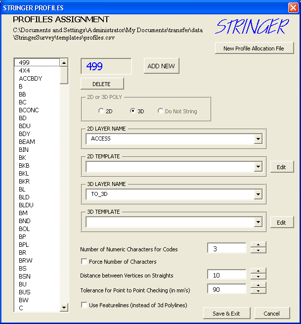
| The profile editor enables the user to tell Stringer
which point codes to connect together with 2D and/or 3D polyline and
also whether or not to apply a template. The data is stored in the
profiles csv file, the default
location of which is ..\Stringer\Templates directory. You
may navigate to a new profile csv file (which does not have to be
called profiles.csv), either in the current folder or across a
network. The folder that the profile csv is located in must also
contain the template files (*.tem).
To edit an existing code, select it in the column on the left and the entry fields to the right will be populated with its data. Any of these parameters can be altered, if required. For each Code entry in the Profile, five parameters can be defined:
A template file (*.tem) is made up of 4 elements per line: horizontal offset, vertical offset, 2d layer, 3d layer. You can have as many lines in a template file as you wish. A typical template file would look like: -0.42,-.035,rd_kerb,TO_3d |
![]()
![]()
Traverse Editor
The traverse editor allows you to take any 2D or 3D polyline and make adjustments to set up the correct traverse. The adjusted traverse can be used to graphically relocate the control points that make up the traverse. These points can then be exported into a CSV file to be used as control points for the balance of the survey.

Use the
![]() button to select a Polyline (2D or 3D). If you select a 3D polyline, additional fields are displayed that show the delta height for the traverse leg and the actual elevation at the vertex of the polyline.
You can name your traverse as required by entering data at the top left
field entry next to
button to select a Polyline (2D or 3D). If you select a 3D polyline, additional fields are displayed that show the delta height for the traverse leg and the actual elevation at the vertex of the polyline.
You can name your traverse as required by entering data at the top left
field entry next to
![]() .
.
To highlight/edit an entry just click on the leg to edit in the table. The cells at the bottom of the form (above showing 133º 29’ 13.6”, 163.3883 metres, etc) can be edited in the cells. As each cell is edited, the traverse is updated on the screen and in the form.
The
![]() button is for accepting the edits to this points. Pressing the
button is for accepting the edits to this points. Pressing the
![]() button takes the traverse back to this point.
button takes the traverse back to this point.
Use the
![]() button to zoom the current leg to the centre of the screen.
button to zoom the current leg to the centre of the screen.
If the
![]() option is toggled on, as a leg becomes current, the display window is
automatically centred on the traverse leg.
option is toggled on, as a leg becomes current, the display window is
automatically centred on the traverse leg.
The
![]() and
and
![]() toggles are for how forward legs of the traverse are effected by edits. For example, if you edited the coordinates of leg
4 (highlighted) while the Hold Coordinates is selected, none of the forward
coordinates are altered. If, on the other hand, Hold Bearings/Distances is selected and you shift the current vertex then all forward
coordinates will be moved. Ditto for Elevation. This is important for where you have identified a gross error and all forward stations need to be moved.
toggles are for how forward legs of the traverse are effected by edits. For example, if you edited the coordinates of leg
4 (highlighted) while the Hold Coordinates is selected, none of the forward
coordinates are altered. If, on the other hand, Hold Bearings/Distances is selected and you shift the current vertex then all forward
coordinates will be moved. Ditto for Elevation. This is important for where you have identified a gross error and all forward stations need to be moved.
![]() Offers cells for entering the actual coordinates of the new vertex. If
Hold Coordinates is true then all forward legs of the traverse are not moved. If
Hold Bearings/Distances is true then all forward legs of the traverse are moved by the coordinate shift. Sets the
Undo Mark to the traverse existing prior to the command.
Offers cells for entering the actual coordinates of the new vertex. If
Hold Coordinates is true then all forward legs of the traverse are not moved. If
Hold Bearings/Distances is true then all forward legs of the traverse are moved by the coordinate shift. Sets the
Undo Mark to the traverse existing prior to the command.
![]() Offers cells for entering the Bearing and Distance to the new vertex. If
Hold Coordinates is true then all forward legs of the traverse are not moved. If
Hold Bearings/Distances is true then all forward legs of the traverse are moved by the coordinate shift. Sets the
Undo Mark to the traverse existing prior to the command.
Offers cells for entering the Bearing and Distance to the new vertex. If
Hold Coordinates is true then all forward legs of the traverse are not moved. If
Hold Bearings/Distances is true then all forward legs of the traverse are moved by the coordinate shift. Sets the
Undo Mark to the traverse existing prior to the command.
![]() Removes the currently highlighted traverse Leg. Sets the
Undo Mark to the traverse existing prior to the command.
Removes the currently highlighted traverse Leg. Sets the
Undo Mark to the traverse existing prior to the command.
![]()
![]()
Appendix A – Installation
Background
The installation program will give the user the option the change the installation path but it is advised that the default location be used as Stringer/Reducer is programmed to read its settings data from the C:\Program Files\CADApps\Stringer\Templates directory. The default location for this software is C:\Program Files\CADApps\...
Stringer can be started from the Stringerc3d menu.
In addition there is an option to copy a practice projects called StringerTutorial2 to C:\CADApps Training Data\Civil 3D Projects. This project can be deleted with Windows Explorer. There is also a backup copy of this project located in C:\Program Files\CADApps\CADApps Training Data Resource\Civil 3D Projects.
Loading the menu file:
The menu file should be loaded as part of the installation for Civil 3D 2005. Early versions of the installation program did not automatically load the menu file, and in some cases automatic display of the menus may not occur. In these cases start Civil 3D and open any drawing.
Type cuiload<Enter>
Select <Browse> and find the file stringerc3d5.mnu located in C:\Program Files\CADApps\Stringer\Programs
Select <Load>
Use the CUI command arrange and save the menu set up as required for future convenience.
Licensing
Stringer/Reducer licensing is implemented with Software provided by FlexLM. The link between the FlexLM Software and Stringer/Reducer is provided by the files ServerName.txt & prjStringerUtility.exe as well as the licence file itself CADApps.lic.
Full documentation of aspects of this licensing system are included on the Installation CD.
Remove the installation
This can be done from:
| The Windows Start menu as a sub item of CADApps | |
| Running the Uninstall program uninstxxx.exe from the Stringer Installation directory. | |
| Using the Windows Add/Remove programs procedures |
Uninstalling the Stringer program does not uninstall the FlexLM licencing which may be required for other CADApps software. If you require this to be removed please contact support@cadapps.com.au for further information
Appendix B - Settings
Settings
Stringer uses the following settings files to control its output.Numeric.dat has four lines of data controlling how the stringing occurs.
Profiles.csv holds the data determining the nature of the strings drawn for each point description. See discussion on the Profile Editor below for an easy method of editing this file.
The files *.TEM are template files. These are used to define the supplementary strings drawn on relevant point descriptions as defined in the Profiles.csv file. There can be an unlimited number of these files.
Treeinfo.dat holds the data used when the Replace Tree command is used to insert tree symbols.
Numeric.dat
Numeric.dat is located in the ...\stringer\programs directory. It defines settings used by Stringer as detailed below. The file contains the following four lines:
- Is a single number and is used to allow the Software to use a referenced number of digits as a point description code. The default value is 3 which is the most commonly used digital coding system.
- Is a single number that represents the maximum (plan) length before a vertex is added to a 3D polyline.
- Is a single number that is the default value for the tolerance when a Point Group to Points comparison is done.
- Is a yes or no entry that is used to either enable/disable to addition of vertices to 3D polylines using the value in line 2 as the maximum length.
Sample of Numeric.dat
3
30
100
yesProfiles.csv
This file is best edited with the Profile Editor, either from the Stringer Import Menu or by entering PROF at the command line. The strings are assigned to layers with template files assigned based on the Point code as defined in the the Profiles csv file. You may nominate the location of the profile csv file. The folder that the profile csv file is located in is where the templates must also be located. The default is for the profile csv file to be called profiles.csv and be located in the Stringer\templates\ folder. You may navigate to a new profile csv file from the Profile Editor menu. Where the file or template provides for 3D drafting, 3D polylines are drawn and can be readily used as breaklines in digital Terrain models.
This file is a comma separated text file holding 6 data items per line as follows:
- Code for the points being strung
- Type of Stringing, either; 1 - Do Not String, 2 - String 2D polylines only or 3 - String 2D polylines and 3D breaklines
- Layer for 2D polylines
- Template file name to use for 2D polylines
- Layer for 3D breaklines
- Template file name to use for 3D breaklines
If a 2D polyline or a 3D breakline is flagged (2 or 3 in the second column) and a layer for both/either is not nominated, then the current layer will be used.
Do not leave any spaces in the data items
Sample data for Profiles.csv
KBL,3,RD_KERB_STD,KBL,RD_3D,KBL
KMR,3,RD_KERB,KMR,RD_3D,KMR
408,3,RD_EOP,KMR,RD_3D,KMR
FN,2,ST_FENCE,,,
CR,3,RD_CROWN,,RD_3D,
CG,3,TO_CG,,TOPO_3D,Template files
These files are comma separated text files containing 4 data items per line as follows:
- Horizontal Offset from Centreline (You may have negative offsets)
- Vertical Offset from Centreline
- Layer for 2D offset line
- Layer for 3D offset line
Do not leave any spaces in the data items
Sample data for a template file
0.15,0,rd_kerb_face,rd_3D
0.2,-0.145,rd_kerb_il,rd_3D
0.60,-0.11,rd_kerb_lip,rd_3DTemplates are used to create parallel polylines to the surveyed line, whether as 2D drafting lines or as 3D terrain modelling breaklines. The template files must have the file extension TEM and must be placed in the ...\stringer\templates directory.
Treeinfo.dat
Treeinfo.dat is located in the ..\Stringer directory. This file is a comma separated file containing details of tree symbols to be inserted into your project, each line has 5 data items as follows:
- Code to look for, you can have multiple codes. For example: as shown below, numeric code users may use 20700 and 21000 for different trees while Alpha code users might use TR.
- Symbol to use if no parameter is given, or only one parameter is given. For example: TR or TR 4 would insert the symbol VE_TREE at a scale 1 or scale 4 respectively (referring to example below).
- Symbol to use for the first parameter if 2 or 3 parameters are given.
- Symbol to use for the second parameter if 2 or 3 parameters are given. For example: TR 0.3 4 would insert the symbol VE_TRUNK at scale 0.3 and VE_SPREAD at scale 4 (referring to example below)
- Symbol to use for the third parameter if 3 parameters are given. For example: TR 0.3 4 6 would insert the symbol VE_TRUNK at scale 0.3, VE_SPREAD at scale 4 and VE_TREE_3D with XY scale of 4 and Z scale of 6.
Do not leave any spaces in the data items
Sample data for Treeinfo.dat
20700,VE_TREE,VE_TRUNK,VE_SPREAD,VE_TREE_3D
21000,VE_TREE,VE_TRUNK,VE_SPREAD,VE_TREE_3D
TR,VE_TREE,VE_TRUNK,VE_SPREAD,VE_TREE_3DFile Search Paths for Resource Files - Replace Tree Symbols and Replace AEC Points Routines
Stringer references external files (blocks) to undertake the Replace Tree Symbols command and the Replace AEC Points command.
In order to locate these files Stringer looks in the following locations (using the first found) for the appropriate blocks (.dwg files):
- Blocks that exist in the current drawing, then
- The Support File Search Paths in Autodesk Civil 3D
By default (on install) the required blocks to run the Replace Tree Symbols command and the Replace AEC Points command are located in the ../Stringer/Data directory.
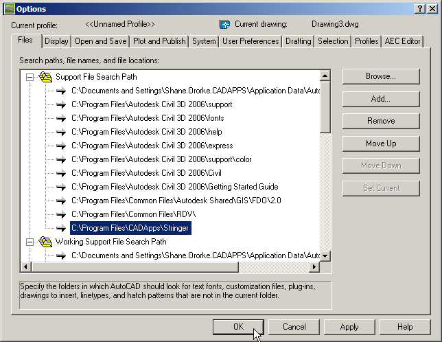
It is strongly recommended that users set up where to locate the resource files and then to add a new Support File Search path in Civil 3D to find them.
To add a new support file search path (this example assumes you are using blocks located in the ../Stringer/Data folder):
- Open the Autodesk Options dialog box by either typing 'op' at the command line or clicking on the Options command from the Tools menu:
- Add a new path and use Browse to set the location as shown above. Click on OK to exit.
These two functions will now work, using the blocks located in the ../Stringer/Data directory.